Drivers, surges and supply quality in motorway and major-artery lighting installations
Why most premature failures originate upstream of the LED and how to protect a motorway and major-artery lighting installation.
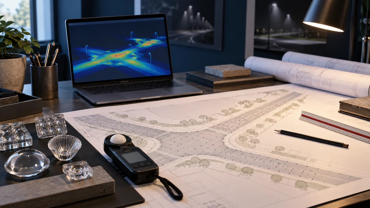
Studio illuminotecnico con planimetria, ottiche e simulazione della luce. Immagine illustrativa generata con AI.
Overview
In LED installation failure statistics the emitter module is rarely the first component to fail: in most cases the problem lies in the driver or in the quality of the network feeding it. On motorways and main extra-urban roads, lighting is concentrated on interchanges, service areas and high-risk sections, where visual continuity is a safety requirement. This Centro Studi Lumeitalia deep dive analyses the mechanisms at play in motorway and major-artery lighting installations and the design countermeasures.
Applicable standards
The regulatory reference for motorway and major-artery lighting is not a single document but a coordinated set of standards covering performance, safety and environmental impact. In design practice the following documents drive the main choices.
EN 13201-2 — M classes for fast motorised traffic.
CIE 140 — road lighting calculation methods.
UNI 11248 — class selection and adaptive downgrading.
Failure mechanisms upstream of the LED
Three phenomena account for almost all premature failures: transient overvoltages of atmospheric or switching origin, thermal stress on the driver's electrolytic components, and closely spaced switching cycles imposed by poorly configured control logic. The first two shorten the filter capacitor's life, the third stresses the start-up section.
In motorway and major-artery lighting installations the relative weight of the three mechanisms changes with site exposure: avoiding abrupt transition zones between lit and unlit sections is the condition most often underestimated at specification stage.
Coordinating protection devices
Surge protection is not a luminaire accessory but a system decision: it must be coordinated across switchboard, line and luminaire, declaring the withstand level at each stage. A protected luminaire on an unprotected line moves the problem rather than solving it; an oversized downstream protection without upstream discharge does not act in time.
The specification should require the declared withstand in common and differential mode, the end-of-life behaviour of the protection device and its fault signalling: an exhausted, silent SPD is equivalent to no protection at all.
Compatibility with control systems
Dimming, remote management and sensors all interact with the driver. Protocol compatibility, the actual dimming curve at low output, behaviour on signal loss and standby consumption must be verified. The check must be done on the driver-controller combination actually proposed, not on generic protocol conformity claims.
Declared power factor and harmonic content must be read at the expected operating power, not only at nominal rating: many installations run permanently dimmed, and under that condition the values change.
Recurring critical points
The difficulties that most often emerge in motorway and major-artery lighting projects are not about product selection, but about defining requirements and verifying results.
Avoiding abrupt transition zones between lit and unlit sections.
Keeping maintenance feasible with minimal lane closures.
Withstanding vibration, de-icing salt and wind loads on high masts.
Design approach
An orderly method drastically reduces variations during works and disputes at commissioning. Three choices make the difference from the earliest stages.
Transition zones designed with a controlled luminance gradient.
Luminaires with fast access to the gear tray and replaceable components.
Remote management for diagnostics and fewer field interventions.
Parameters to verify
M class — EN 13201-2 — assigned by design speed and complexity
Surround ratio SR — EN 13201-2 — lighting of the lateral strips
Maintainability — specification — access without removing the optic
Mechanical resistance — EN 60598 — vibration and pole loads
Most frequent mistakes
Non-conformities found at commissioning almost always come from three causes: requirements not declared or declared without a reference standard, calculation run on idealised geometry, and an optimistic maintenance factor. All three can be avoided at zero cost during design.
Surge protection levels coordinated across board, line and luminaire
Declared common- and differential-mode withstand verified
SPD end-of-life behaviour and signalling specified
Dimming curve verified at low output levels
Behaviour on control signal loss defined
Power factor and harmonics assessed at operating power
Key takeaways
A motorway and major-artery lighting project holds up over time when requirements are declared, the calculation reproduces real conditions and on-site verification follows an agreed protocol. Component selection matters, but comes later: without measurable requirements even the best product delivers a result that cannot be demonstrated. Centro Studi Lumeitalia makes its technical office available to review requirements and design checks.
Methodological note: This content is written for technical information purposes by Centro Studi Lumeitalia and does not replace the lighting design or a full reading of the standards cited. Applicable performance values are those of the standards in force at design time.
Domande frequenti
Why are motorways not lit end to end?+
Because continuous lighting is not always the most effective safety measure: standards and design practice concentrate it on interchanges, conflict areas, tunnels and sections with documented accident rates.
How is the transition between lit and dark sections handled?+
With a transition zone of decreasing luminance, allowing the driver's visual adaptation and avoiding the black-hole effect.
Where should a motorway and major-artery lighting project start?+
From a written definition of performance requirements and verification conditions: this step drives every later choice and makes the result either disputable or defensible at commissioning.
Which documents should be requested from the supplier?+
Photometric files of the proposed luminaires, declaration of conformity, lifetime data declared per IES LM-80 with its conditions, the maintenance schedule and warranty terms.
Lumeitalia — Sistemi LED professionali
Lumeitalia è il brand di illuminazione LED professionale di Mya Tech S.r.l., azienda italiana fondata nel 2011 a Trezzano sul Naviglio (MI); il brand è attivo dal 2020.